1. Verilog Language
1. Basic
Wire
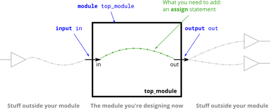
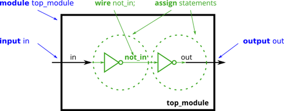
使用连续赋值 assign 将左边连至右边,就像导线一样. Verilog 在定义 input 和 output 时可以省略 wire,即相当于input wire in, output wire out.
1
2
3
| module top_module( input in, output out );
assign out = in;
endmodule
|
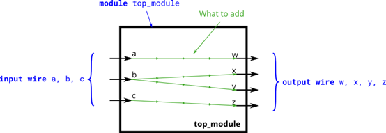
Wire4
1
2
3
4
5
6
7
8
| module top_module(
input a,b,c,
output w,x,y,z );
assign w= a;
assign x = b;
assign y = b;
assign z = c;
endmodule
|
Notgate
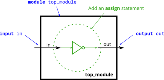
逻辑取反 ! 和按位取反 ~ ,前者只能用于一位的信号,即!1=0, !0=1,在电路中对应一个反相器; 后者还可用于多位宽的信号,如~101=010。
1
2
3
| module top_module( input in, output out );
assign out = !in;
endmodule
|
Andgate
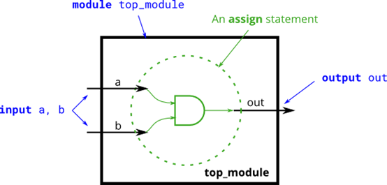
按位与 & 和逻辑与 &&
按位与就是正常的
逻辑与是只有 1111 && 0000 才为0
有一个1 就不是0
Norgate
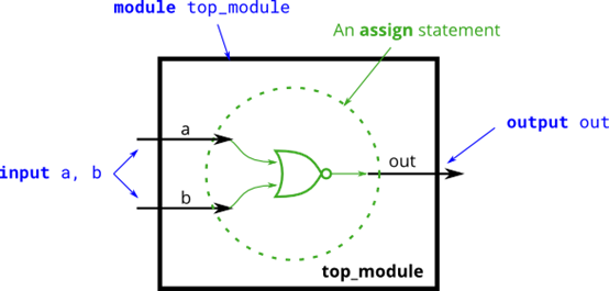
或也有按位或 | 和逻辑或 || 同上
Xnorgate
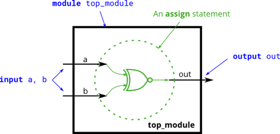
XNOR 同或 相同吗? ~^
XOR 异或 不同吗? ^
只有按位没有逻辑xor xnor
Wire decl
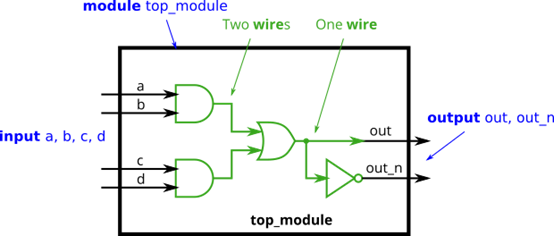
有时在模块内需要自己定义wire作为中间量 注意wire只能由一个信号驱动
1
2
3
4
5
6
7
8
9
10
11
| module top_module (
input in, // Declare an input wire named "in"
output out // Declare an output wire named "out"
);
wire not_in; // Declare a wire named "not_in"
assign out = ~not_in; // Assign a value to out (create a NOT gate).
assign not_in = ~in; // Assign a value to not_in (create another NOT gate).
endmodule // End of module "top_module"
|
1
2
3
4
5
6
7
8
9
10
11
12
13
14
15
16
| `default_nettype none
module top_module(
input a,
input b,
input c,
input d,
output out,
output out_n );
wire and1,and2;
assign and1 = a & b;
assign and2 = c & d;
assign out = and1 | and2;
assign out_n = ~out;
endmodule
|
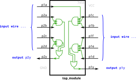
7548
1
2
3
4
5
6
7
8
9
10
11
12
13
| module top_module (
input p1a, p1b, p1c, p1d, p1e, p1f,
output p1y,
input p2a, p2b, p2c, p2d,
output p2y );
wire and1,and2,and3,and4;
assign and1 = p2a & p2b;
assign and2 = p2c & p2d;
assign and3 = p1a & p1c & p1b;
assign and4 = p1f & p1e &p1d;
assign p2y = and1 | and2;
assign p1y = and3 | and4;
endmodule
|
